This page has been translated with google translate, there may be errors in the stories
Install auxiliary relay starter motor Yanmar. If an extension cable tree is used with a Yanmar engine, an auxiliary relay must be installed, this is described in the service manual.
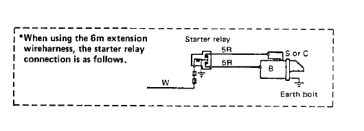
The best is a relay with built-in fuse, if for some reason something goes wrong in the starter motor, the thin wires from point B (picture above) are protected by the fuse, this reduces the risk of fire.
This is a nice relay for this available in the web store of this site.
Connection is the same for every yanmar. A wire from the + of the starter motor to the relay, and from the relay to the S or C connection on the starter motor (starter relay), this is the main power circuit.
The wire that comes from the start button or ignition switch is disconnected from the starter motor (start relay) and connects to the auxiliary relay and then another wire from the auxiliary relay to the minus.
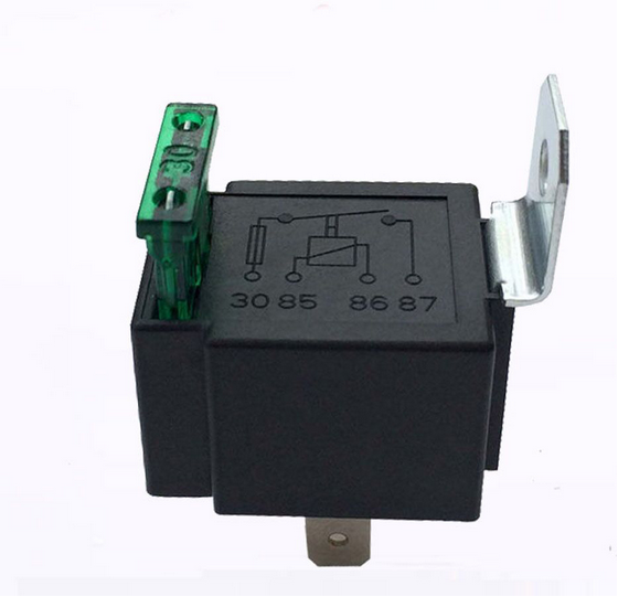
What do you connect to what:
Connection 30: wire from the + starter motor (B)
Connection 87: wire to the starter motor (S or C)
Connection 85: wire from starter button / ignition lock
Connection 86: wire to the min
n.b. The wire on connection 85 is removed from the starter motor and connected to the relay.
What does that look like in practice now:

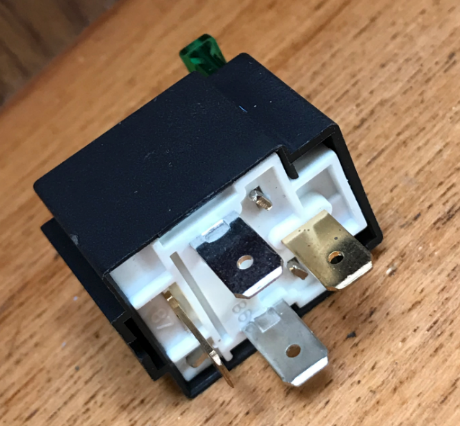
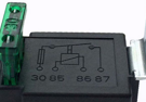
The relay. The Bottom: Here are the numbers at the connections.
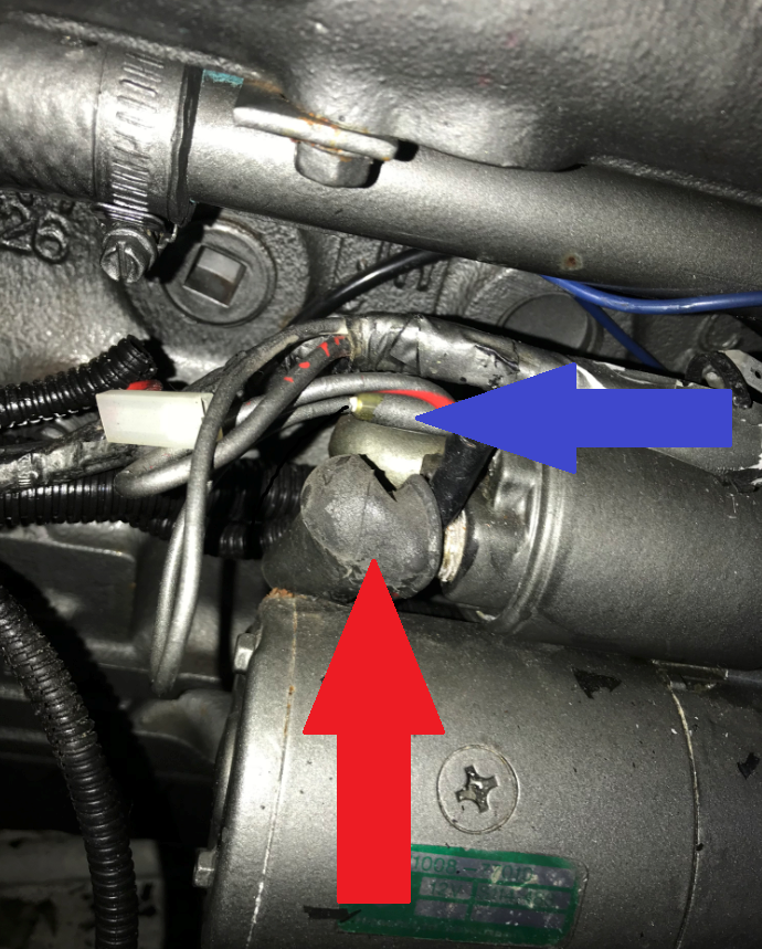
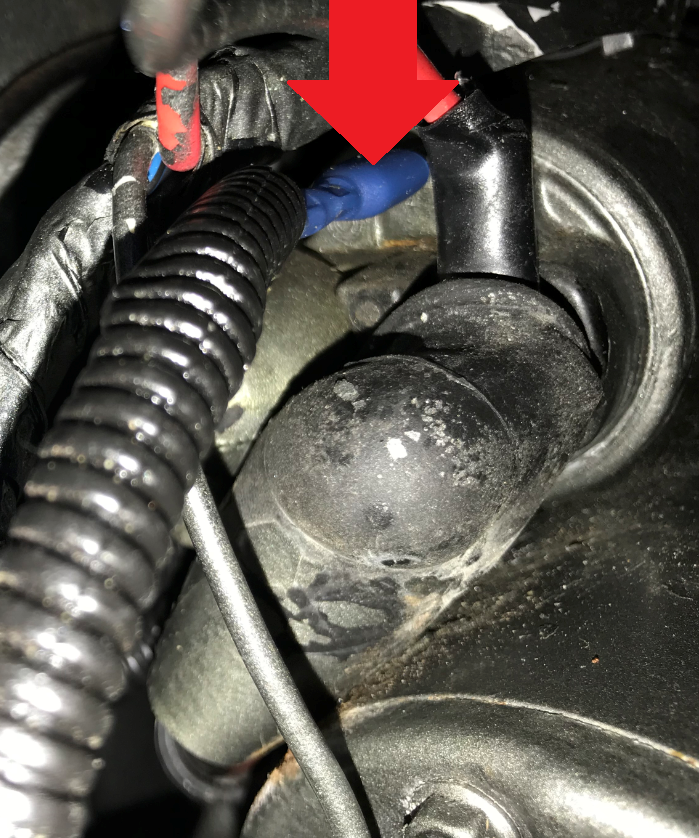
The blue arrow is the wire from the starter button / ignition lock.
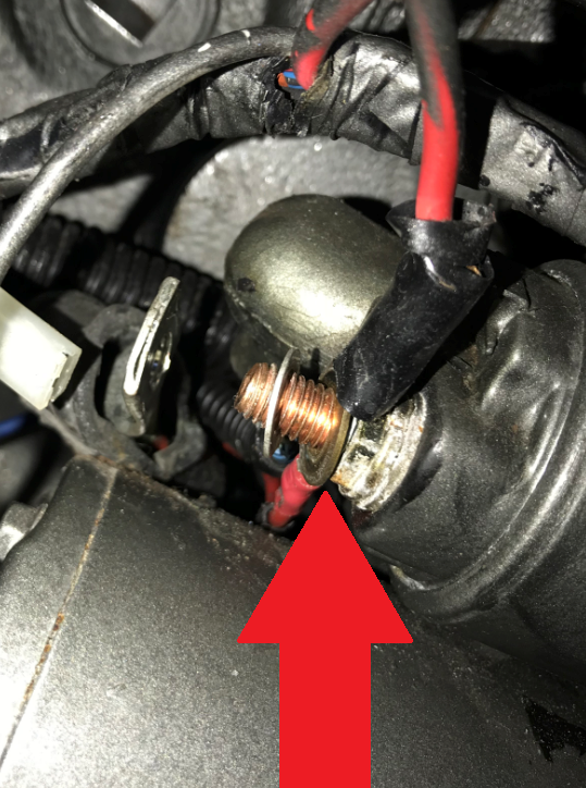
The red arrow indicates the + connection of the starter motor.
A close up of the starter relay, the rubber cap has been pushed aside, you can now clearly see the + connection of the starter motor and the wire of the starter button / ignition lock.

In this example there is a wire from the + connection of the starter motor mounted, this is for the stop device.
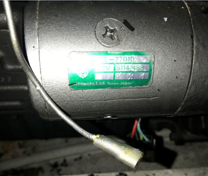
The wire coming from the start button / ignition switch disconnected.
Make a wire that goes from the + of the starter motor to terminal 30 of the auxiliary relay.
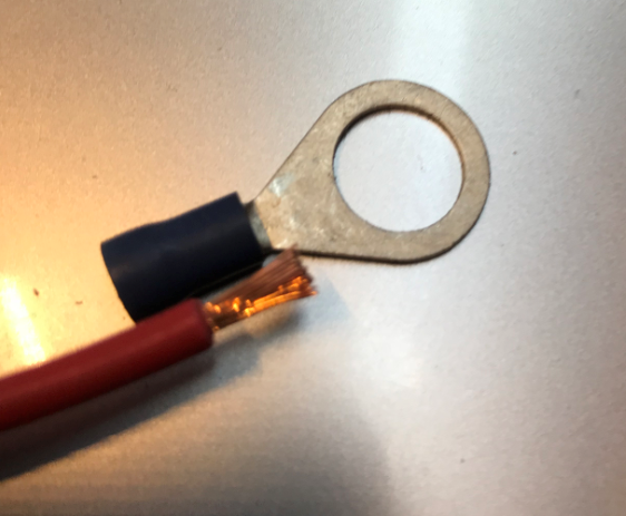

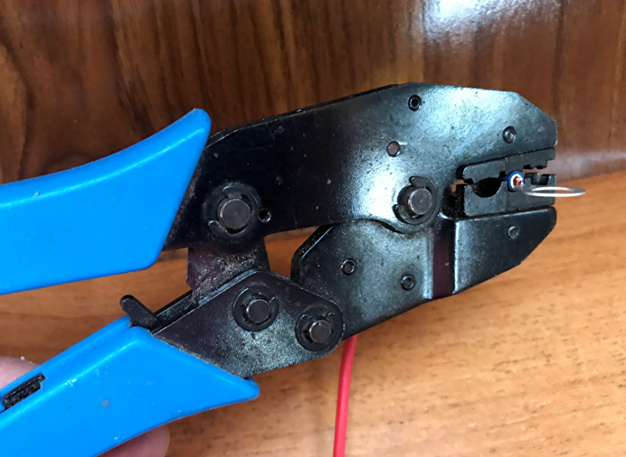
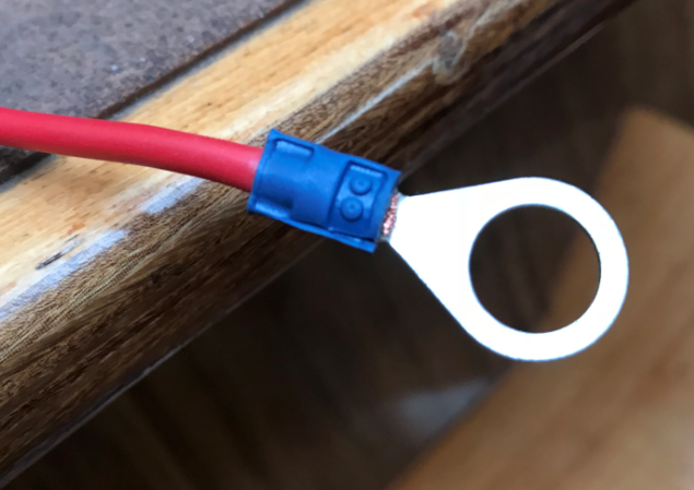

The cable eye is placed on the + of the starter motor. The cable shoe is placed on the auxiliary relay.
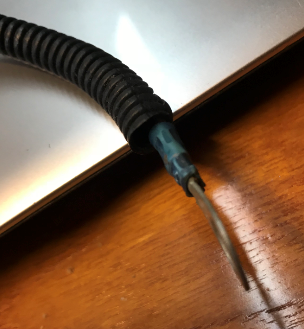
For extra protection of the wire, you can apply a protection tube around the wire.
Make all the wires needed.
Cable eye - cable shoe + starter motor to connection 30 auxiliary relay, color red
Cable eye - cable lug minus for example on the engine block to connection 86 auxiliary relay, color blue
Cable shoe - cable shoe starter motor (relay) connection C or S to connection 87 auxiliary relay. Color nb.

You mount the wire with cable eye behind the cable shoe.
Auxiliary relay wire.
Tyrap all cables and wires together. Tyrap the auxiliary relay to the cable harness.
Make sure that the fuse is easily accessible.
The relay connections mentioned in this report are only valid for the relay used for this report, always check the connections on the relay you are applying.