This page has been translated with google translate, there may be errors in the stories.
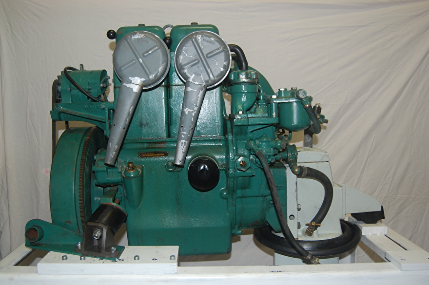
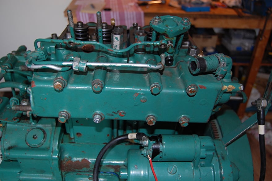
I have started a new project and that is the revision of a Volvo Penta MD11C I recently bought (05-2013).
this MD11C comes from a sailing boat that was scrapped because it was negligible and could no longer be sold.
With this project I want to show how you can perform various jobs on your engine, for example valve stems, replace head gasket, replace piston rings, etc.
First I made a mobile table, where the MD11C fits nicely, so I can easily move the MD11C and I have a good working height.
The first thing I will do is determine the condition of the engine and there are various measuring methods for this.
1 The compression test.
This allows you to determine the condition of the cylinder and whether the correct combustion pressure is still there. The compression pressure of this engine is 20 to 25 bar.
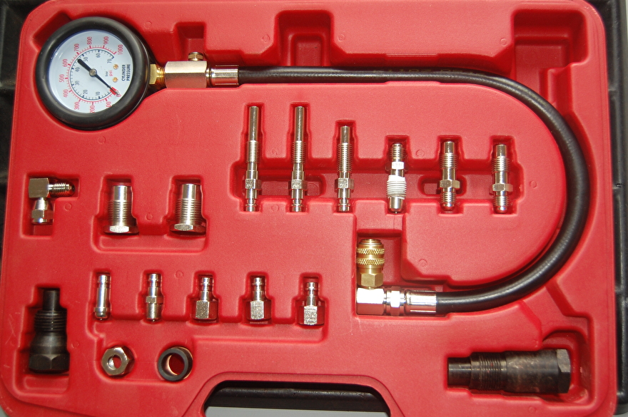
Compression meter set.
2 The leak test.
You can also perform a leak test with a leak tester, here you also need a compressor. This device has a meter with a scale in percent and the more percent the meter reads, the more the cylinder / valves are leaking. Now zero leakage is not possible, even with a new engine, but 20 percent is not serious for a diesel. Because you perform the test with air, you can also easily find the place or places where the compression loss comes from. This may be due to the piston suspension being worn or the loading or unloading valve not closing properly, both are of course also possible.

Leak test set.
3 Temperature gauge.
The problem with directly cooled marine diesels is that over time the cooling channels slip and the engine gets too hot. Although the temperature gauge on a dashboard of the engine indicates that the engine is not too hot, it may be that the engine is still too hot in certain places. It is often the case that there is no longer a good flow of cooling water around the cylinders due to the cooling channels slipping shut.
This is a gradual process that you should actually be ahead of before the cooling water alarm goes off and you cannot go any further.
With an infrared meter you can see where the engine is getting too hot with a simple push of a button.

The infrared meter is for sale in the web shop of this site.
Temperature test.
The temperature of a directly cooled engine should be 60 degrees, higher causes scale. Over the years, the cooling channels of directly cooled engines slip, which can only be opened again by removing the head of the engine.


Measure at different points on the block.
It is reason to measure the temperature of the motorcycle at different points on your motorcycle once a year with an infrared temperature meter, but do this with a warm engine block and not warm up in the box. For example, it would be nice that you do this after a day of sailing.
Leak tester.
A leak test is preferably done with a warm engine and you need a dummy spray for it or in my case a self-made tool to which I screw the nipple of the leak tester. If you have a glow plug in the head of the engine, you can connect the leak tester to it, there are two adopters in the set.
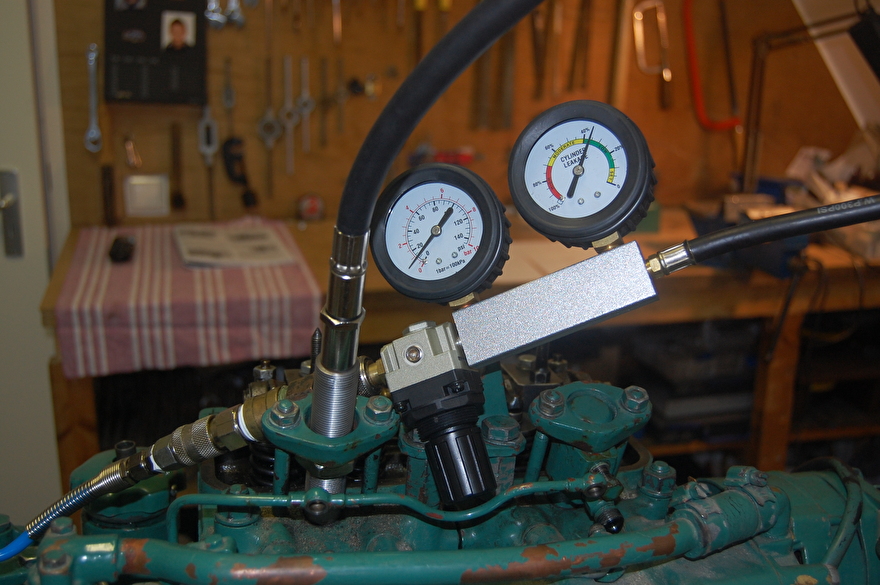
In this photo you can see how the leak tester is connected to the motor.
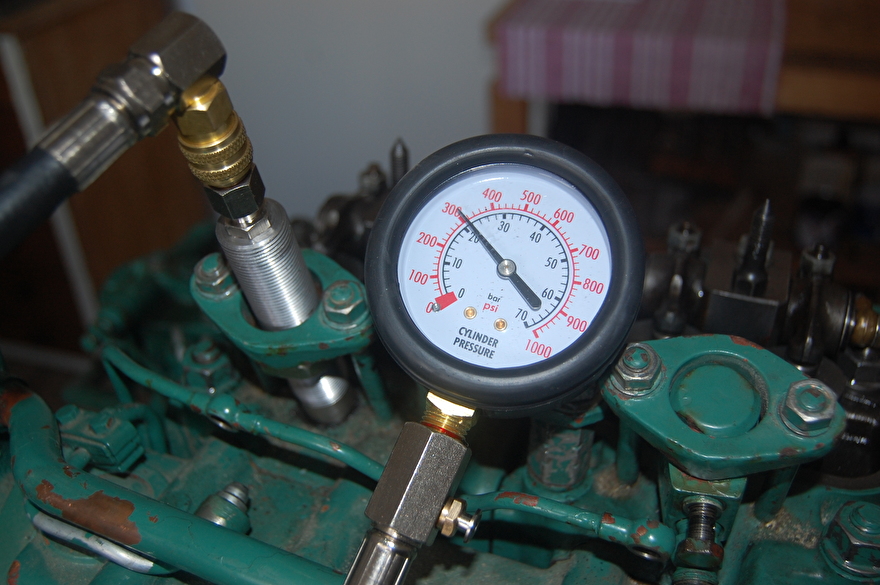
I will start with the compression test and compare the values of both cylinders with the factory values. The compression test is performed with a diesel compression meter and for this I made a self-made adapter because this engine has no glow plug in which I can screw the included adopters. Take the test several times to avoid measurement errors and take the average of, for example, 4 measurements. In order to get a correct measurement it is important that the adopter does not leak. Run the starter motor about 6 revolutions and write the readings and repeat the test several times.
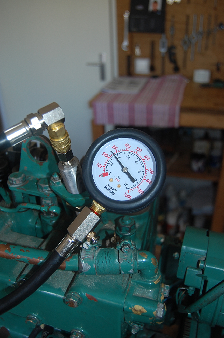
Here a photo of the compression gauge on cylinder 1. The gauge indicates 18 bar and that is not even more traffic for an engine of its 35 years old. 20 to 25 was reported as a new value by the manufacturer.
491/5000
Cylinder 2 indicates a different value, namely 22 bar, the difference between cylinder 1 and 2 is more than 10 to 15 percent, this means that it can cause problems in the operation of the engine such as poor starting, vibration and more smoking.
After I have done the compression test, I will perform the leak test to determine where the compression loss comes from, the piston rings and or the valves. the piston of the cylinder being tested must be in the TDC (Top Dead Point)
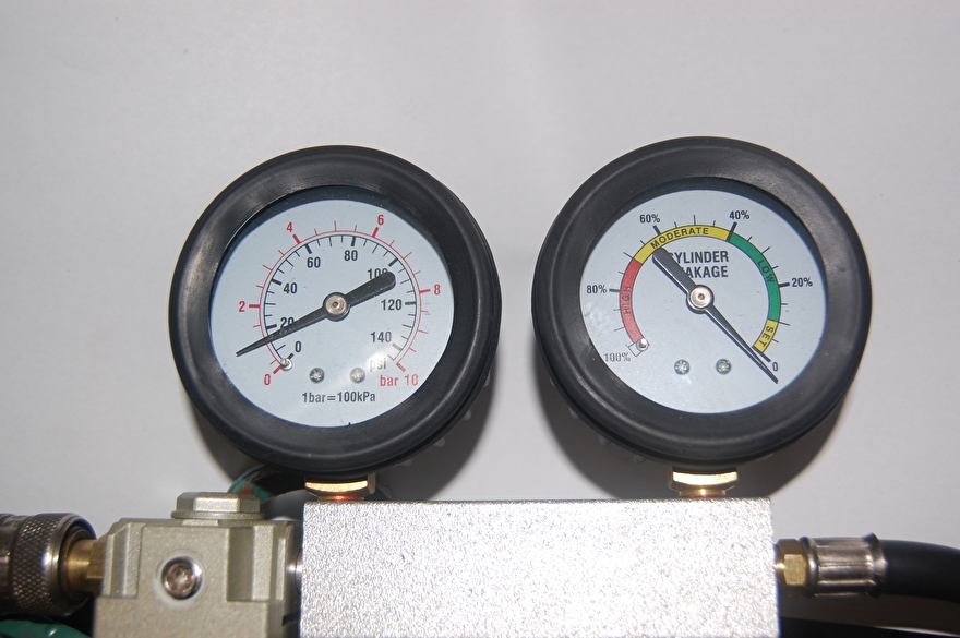
I connect the set to a compressor and adjust the right pressure gauge to zero with the control knob attached to the tester. Then I connect the tester to the adapter that is in the head of the motor and now read the values that are on the right meter.

The meter reads to 30% and has a leak of 30%, which is not even that bad for a 35 year old diesel, but I want to reduce this to 15 to 20% by grinding the valves again and honing the cylinder. and new piston rings. Because air is blown into the cylinder, this will be audible if, for example, an exhaust valve does not close properly, you will hear the air escaping through the exhaust and the same applies to the intake valve, which will then leak to the air filter. If the piston rings no longer seal properly, air will leak to the crankcase and you will hear this in the crankcase breather or if you remove the dipstick.
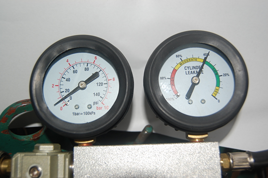
Cylinder 2 is a bit worse and for this test again the difference between two cylinders should not be more than 10 to 15%.
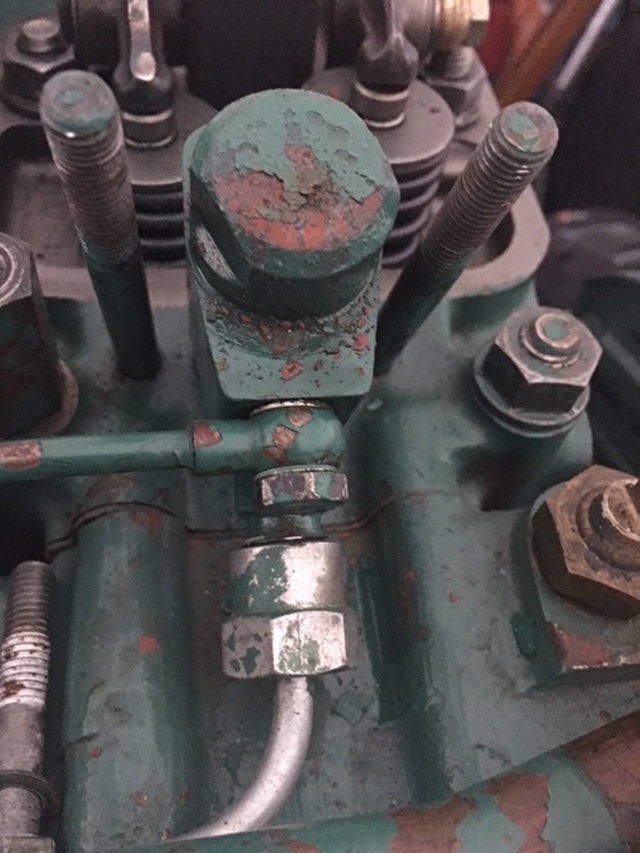
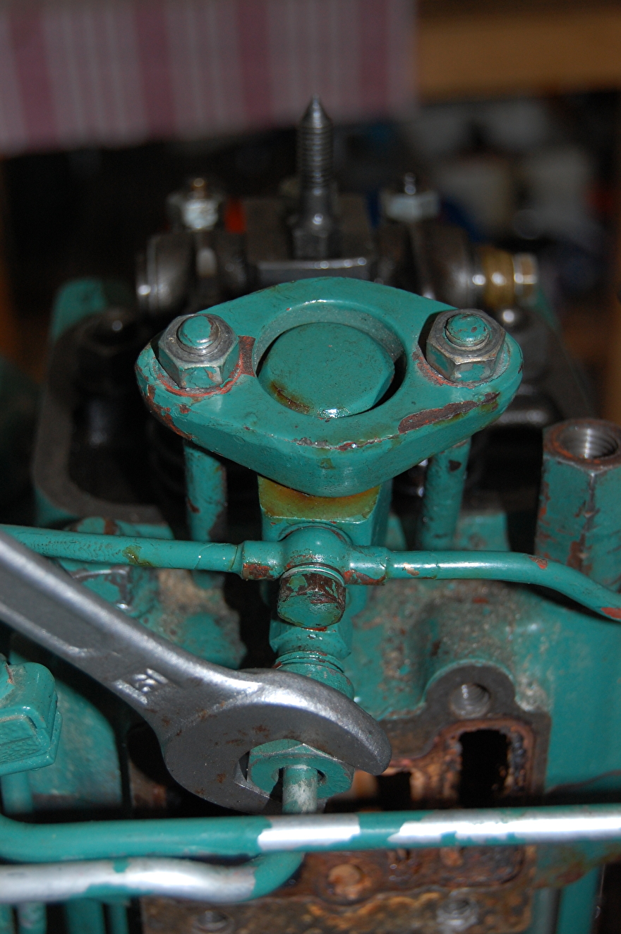
Remove cylinder head and water-cooled manifold.

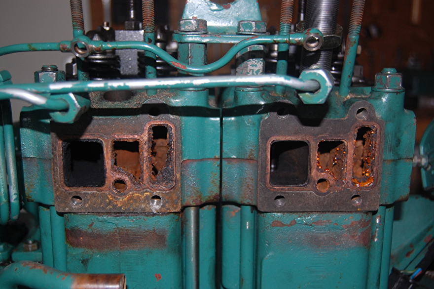
Loosen the cooling hose under the manifold and remove the 8 bolts from the manifold.


To be able to remove the head, the oil pipe to the valve rocker arms must be disconnected and the valve rocker system, if these are loose, the head bolts can be removed.
What is important is that the parts are kept together so that you can not mix them up with the parts of the second cylinder.
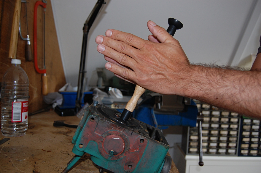
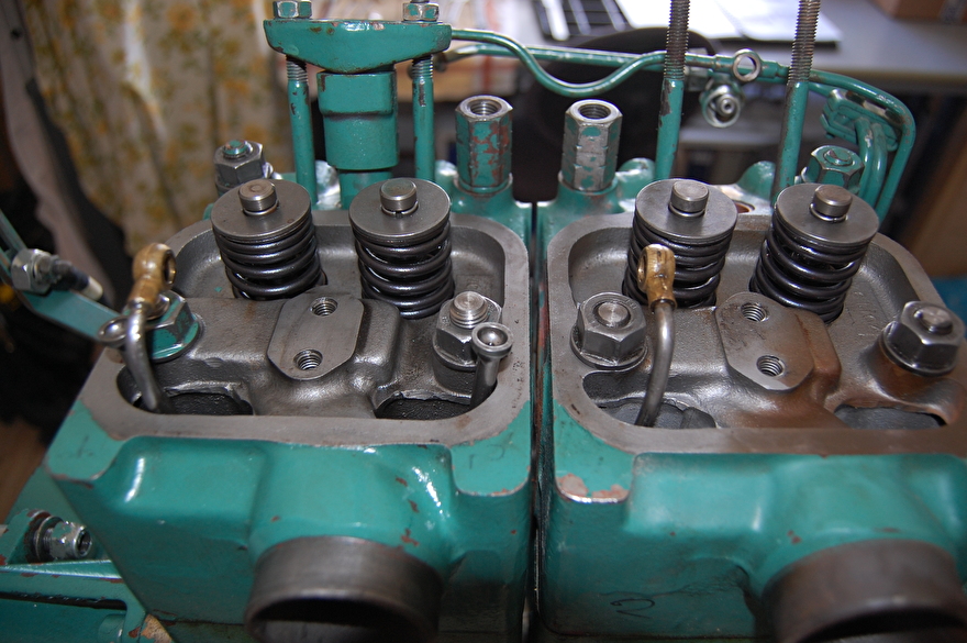
Now that the head is on the workbench, I am going to remove the flaps, for this there is special tools, but I will show you a different way that can be done by most handymen.


Put the head in the vise and put 2 bolts against the cymbal and the spring plate, slowly close the vise until you can see the half gimps around the valves. Remove the skewers and open the vice again.

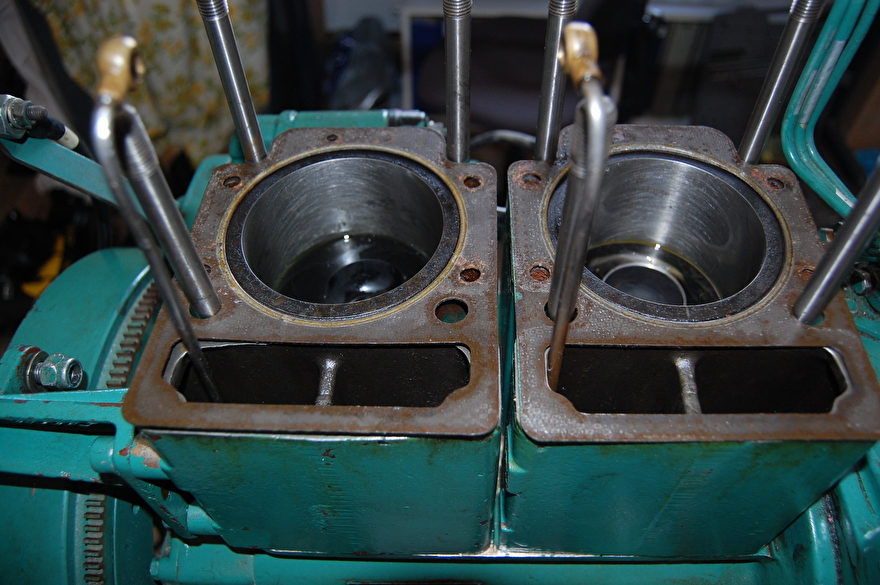
Now that the valves have been removed, you can clearly see how the seats have been damaged.
Grind valves and seat.


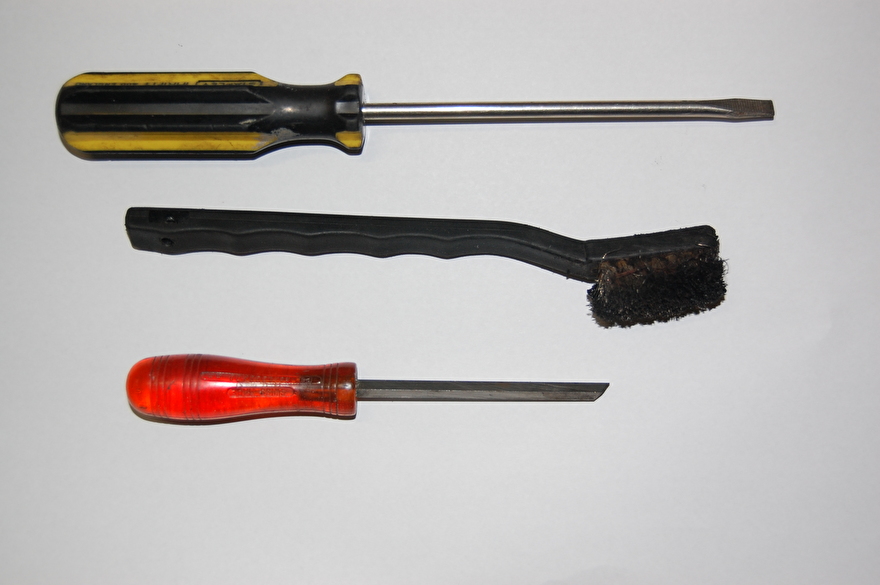
To sharpen the valve and the seat you need a grinding paste and a stick set.
In order for the stick to stick to the valve, the valve must first be clean, otherwise the suction do not hold the suction cup.


You can do this by putting the valve in the drill and holding a piece of sandpaper against the valve, but be careful not to touch the valve seat while sanding.

Press the stick against the valve and put some sanding paste on it, I start with coarse and when the valve seat looks neat again I use the fine paste to polish.
Sand the flap with two hands around the stick and turn the stick after and sand several times 90 degrees to get a nice even image and use new paste every now and then, but first make the flap and the seat in the head again clean.

See the difference between the two valve seats.
Met de link komt u bij de klep slijpset die ik heb gebruikt.
Leak test.
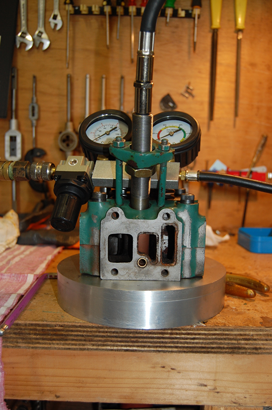
To do the leak test I made a mold outside the engine on which the head is bolted and use a piece of gasket to seal the head, you can also use an old navigation map.

Again a leak test done and the meter is now at 12% and I hear no more air leaking through the valves, so the rest of the leak goes through the piston rings but more about that later.

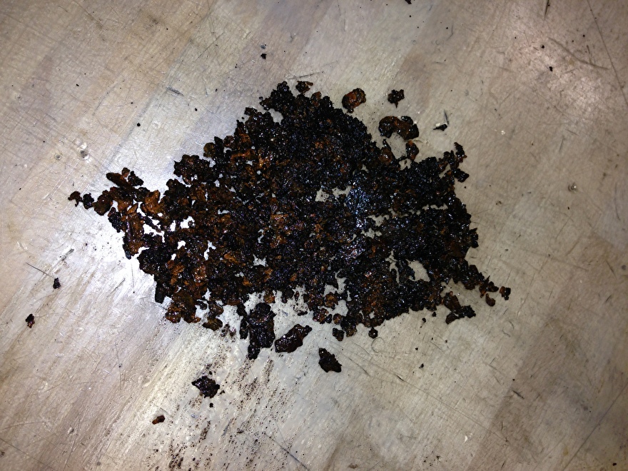
The cooling channels of the head are fairly closed and I drill these by hand with a drill around 8mm and descale the head further with descaler. Oxalic acid is a great way to remove lime, but especially rust, from the cooling channels.

The head is ready to be mounted again. Use a new head gasket when you replace the head.
Injector.
A head revision is only really complete if the injector has also been checked and possibly overhauled if necessary.
To determine the condition of the injector, it must be tested with an atomizer tester.
With this injector tester you check 3 things.
1 The opening pressure at which the nozzle needle is lifted.
2 The injector drips.
3 The injector exhibits characteristic cracking.

The injector.
Step1.

Measure the opening pressure and see if the atomizer drips.
I have written the revision of the atomizers in a separate piece, see link
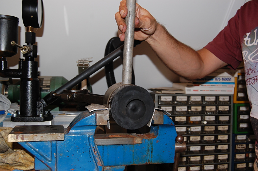
Squeeze the cylinder sleeve and reassemble.
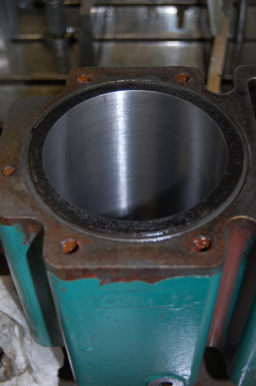
Squeezing the bushes is done with a press, but before the cylinder bush is actually squeezed, it is wise to mark the cylinder bush with a scratch pen so that the lining can be squeezed in the same place (pushed). If you do not do this, it is possible that the engine will consume more oil because the cylinder can be slightly oval, then the piston rings will no longer close properly. If you let the cylinder be machined by machine, this is less important, but it is always wise to mark everything that you remove so that it is reassembled in the same place.

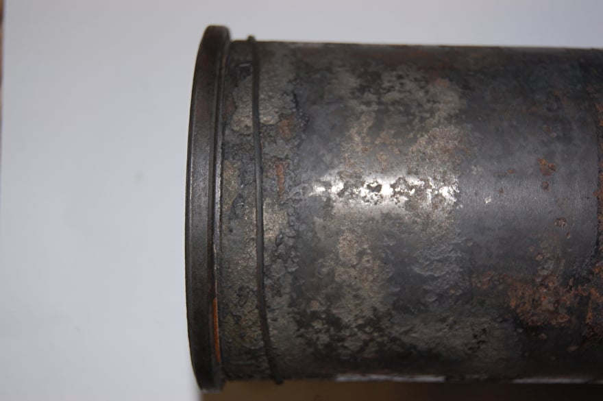
The first step is to press the cylinder sleeve out as far as possible.

With a round plug that is smaller than the external diameter of the cylinder sleeve, you press the jacket out.


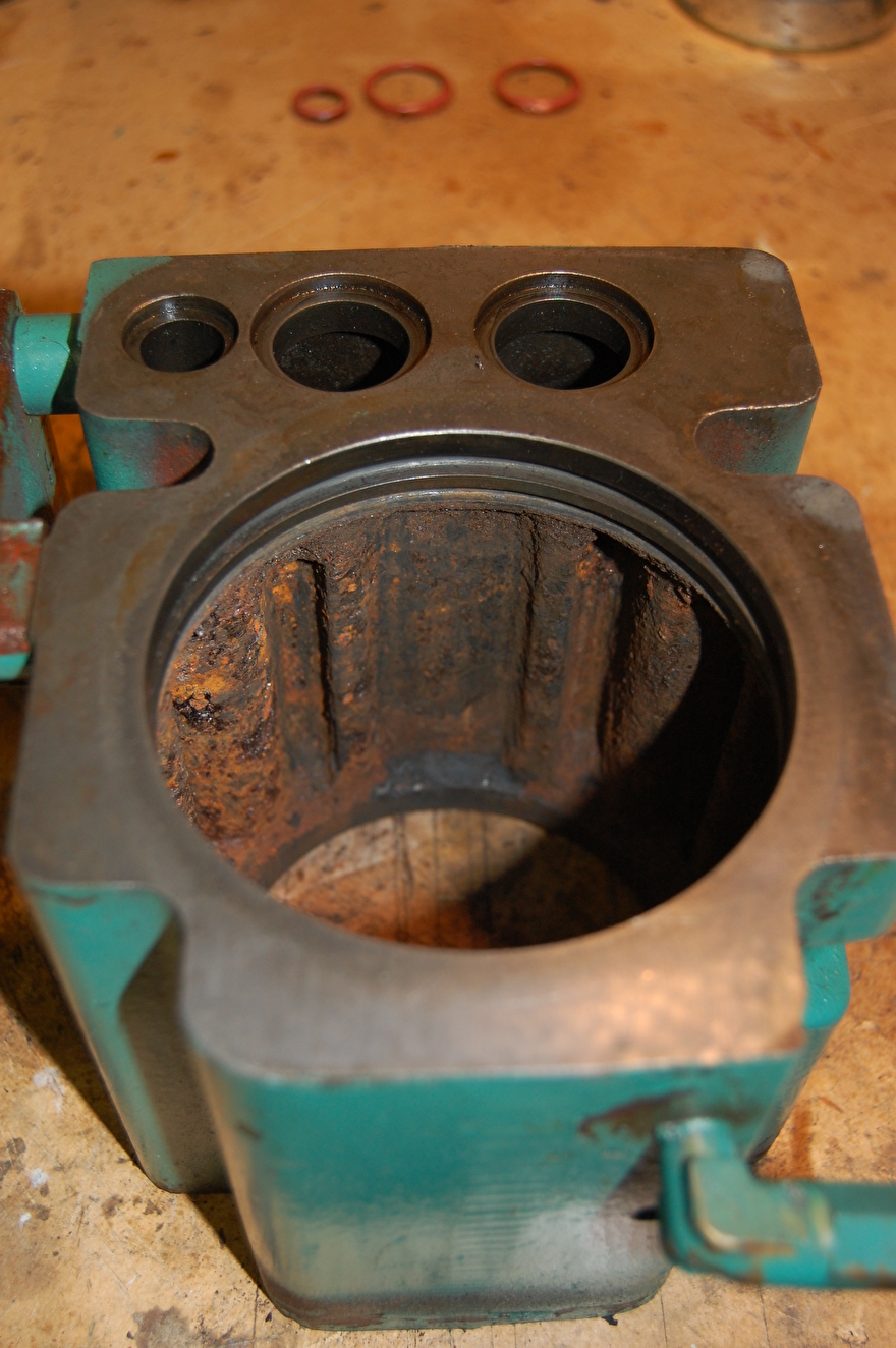
After squeezing the cylinder sleeve and the cylinder block can be cleaned, the photos show something that it is not an unnecessary luxury to take things apart. If it is not possible to squeeze the cylinder sleeves with an engine, you can treat the cooling channels with oxalic acid, I also do this with the water-cooled exhaust manifold and the head of the engine.
I clean the casing and block with a scraper and a wire brush, but care must be taken that the fitting surfaces on which the cylinder can seals are not damaged by cleaning.

O-ring around the cylinder sleeve. Two o-ring in the cylinder block.
The jacket is sealed by 1 O-rings and 2 tendons and these seals really need to be replaced when the jacket is pressed out. There are 2 white tendons in the block and 1 O-ring around the jacket at the top of the neck of the cylinder jacket.

The new seals.
The installation of the tendons, O-ring and the cylinder sleeve must be done cleanly and accurately to prevent the cylinder jacket from leaking when the engine is reassembled. Grease the O-rings a bit, this makes mounting the cylinder sleeve easier.
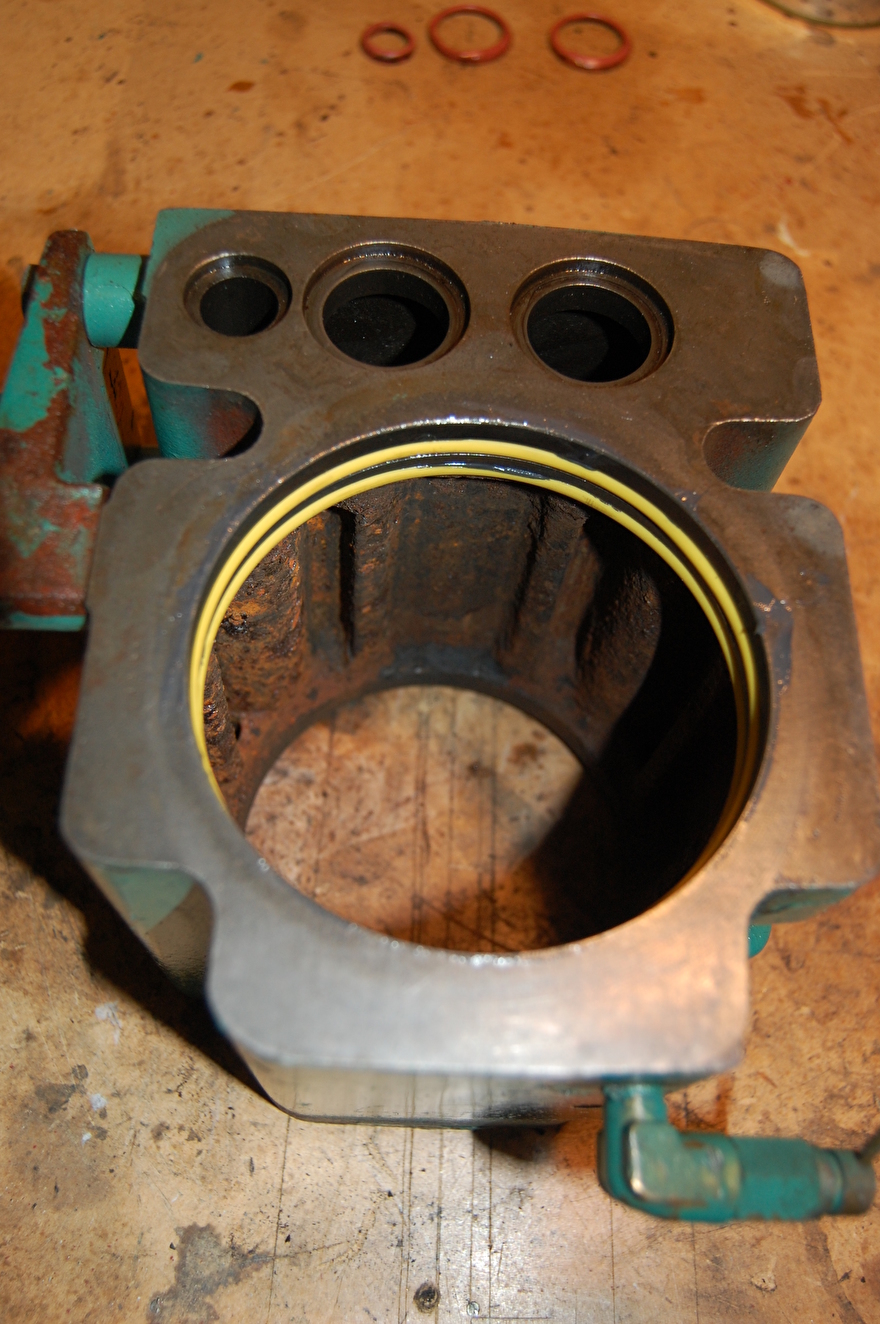
The O-rings grooves must be absolutely clean and then the O-rings can be mounted with some grease.

A thin O-ring is also placed on the edge of the cylinder sleeve.

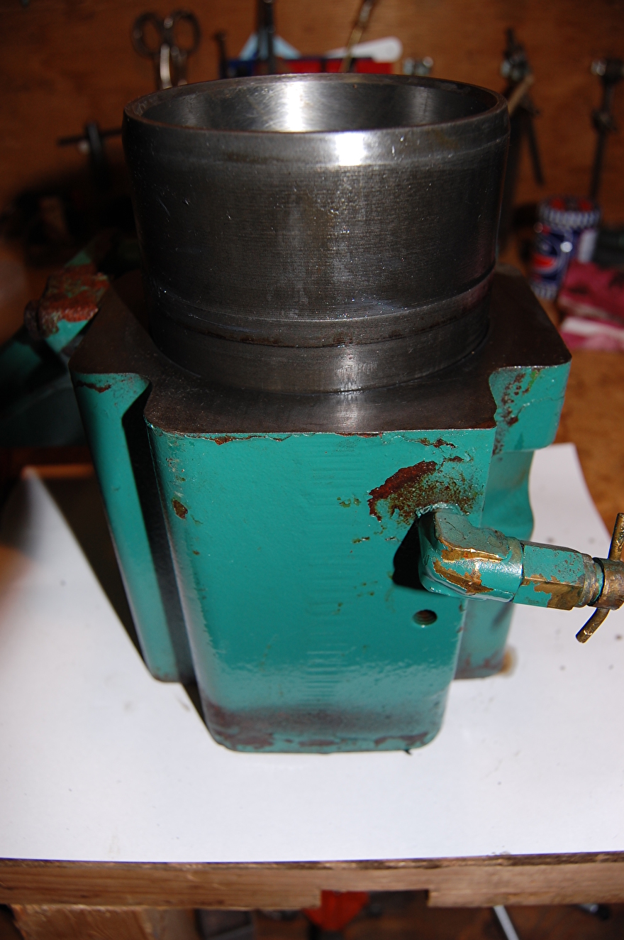
After placing the seals, the cylinder sleeve is placed upside down on the workbench to push the cylinder block over the cylinder sleeve, but care must be taken not to twist or move the O-rings.
Measure cylinder for wear.
When the cylinder sleeves are replaced, the cylinder is measured.

When the cylinder sleeves are replaced, the cylinder is measured.
Machine cylinder.
Honing the cylinder can be done in different ways. On a honing machine with adjustable honing where you actually remove material from the cylinder canister, or with a tripod with honing stones. The last way I chose because the cylinder had no bumper and only a carbon rim and some light scratches.

I did the honing on a machine where we do this more often, because this machine is equipped with an oil pump to lubricate the hone and rinse away dirt and I can more easily fix the cylinder on the table.
Bij het honen moet je een paar dingen in de gaten houden, dat je niet te hard draait met de hoonstift 500/750 omw en dat je de hoon goed over de hele lengte van de cilinder bus heen en weer haalt en niet laten stilstaat op een plek terwijl de hoon draait.
After honing you see a nice honing image in the cylinder, but although it looks neat, the cylinder is now too smooth and needs to be roughened to prevent glazing and excessive oil consumption.


I roughen it up with a Felx-hoon, this hone marker should not rotate too fast and should not rotate in one place, you have to make sure that a cross honing image of 120 gr gets in the cylinder wall.
Remove the connecting rod and piston rings.

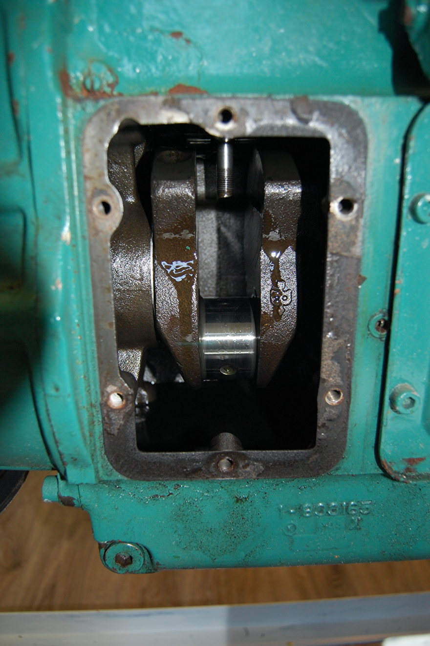
To disassemble the piston rings and check the bearings of the connecting rod for wear, the connecting rod must be removed. To access the connecting rod bearing, the cover must be removed and the nuts of the bearing shell must be turned.
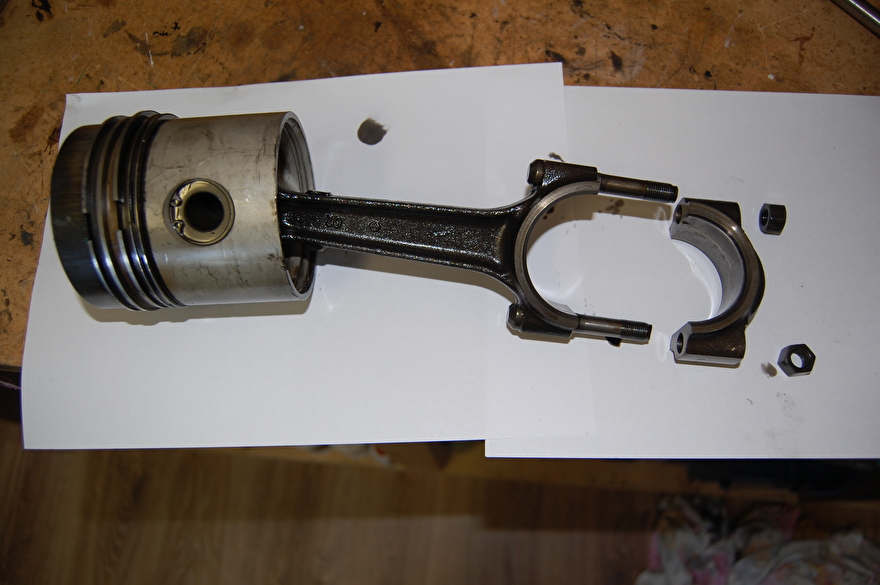
The connecting rod on the workbench. take care not to mix up the nuts, all parts must always be reassembled in the same place.
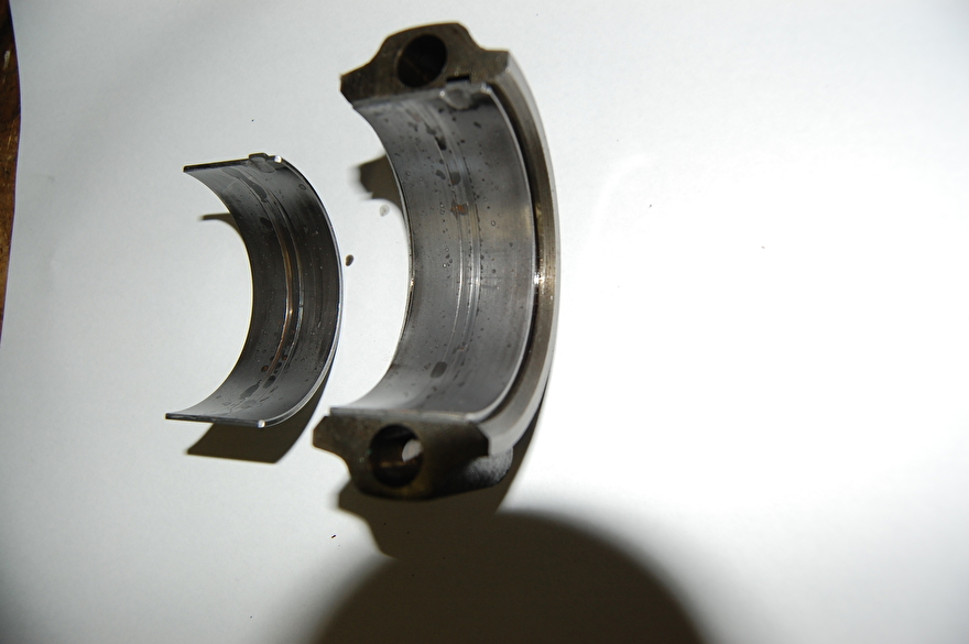
Damage is clearly visible on the shell parts. This may be due to, for example, that the maintenance was not really in order in terms of oil change, but too high an oil pressure can also cause damage to the bearing shells. The latter has not yet been measured and I will measure it when the engine is assembled again.
Replace piston rings.
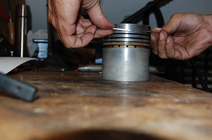
Now that the piston is out, I can measure the play of the piston rings to assess whether they need to be replaced.
There are two measurements:
1 Axiale speling, dit is de speling die de zuigerveer heeft in de groef. Dit wordt gemeten met een voelmaat en moet tussen de 0.08mm en de 0.11mm zitten voor de eerste compressieveer.

2 The clearance clearance measured with the piston ring in the cylinder and must be between 0.4mm and 0.55 mm.
If the piston rings are out of tolerance or the cylinder has been honed, the piston rings must be replaced.
I will explain how the piston rings have been removed as you saw above with the measurement of the lock clearance.

I clamp the connecting rod in the vise and then remove the piston rings. Make sure you put the piston rings in order because you should not mix them up with each other.


Step 1.
Removing the piston rings.

Piston rings arranged in order.
To check the play of all slide bearings it is necessary to remove the piston from the connecting rod.
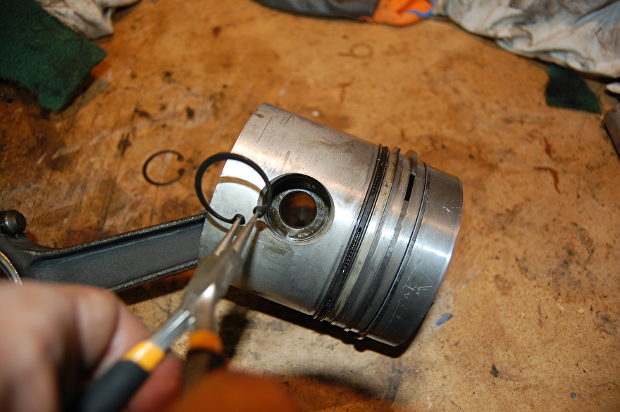
Step 2.
Remove the circlips from the piston with needle-nose pliers.

Step 2.
Tap the pen out of the plunger with a piece of bar stock.


Piston cleaned. All parts in order.
I have now reached the point of partly reassembling the engine. I deliberately did not remove the crankshaft because the engine is now being prepared for the upcoming diesel courses.
When assembling it is important that the work is clean and accurate and that all nuts and bolts are tightened with the correct tightening torque.
Installing the piston rings and connecting rod.

The new piston rings are mounted by bending them open and pushing them over the piston. I start with the lower compression spring and then the subsequent springs, the oil scraper spring comes last.
I turn the piston over and insert the oil scraper spring.
The compression and oil scraper spring back into place.

I use some oil to make assembly easier.
Connecting rod pin partly mounted in the piston.

The connecting rod is put back and all moving parts briefly lubricated with some oil.

The two circlips are replaced. The piston rings and the connecting rod are reassembled.
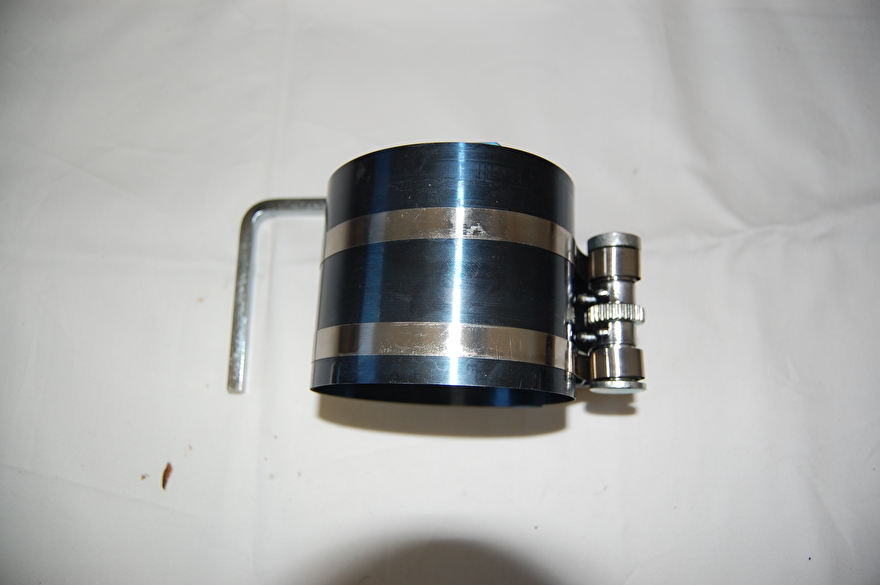

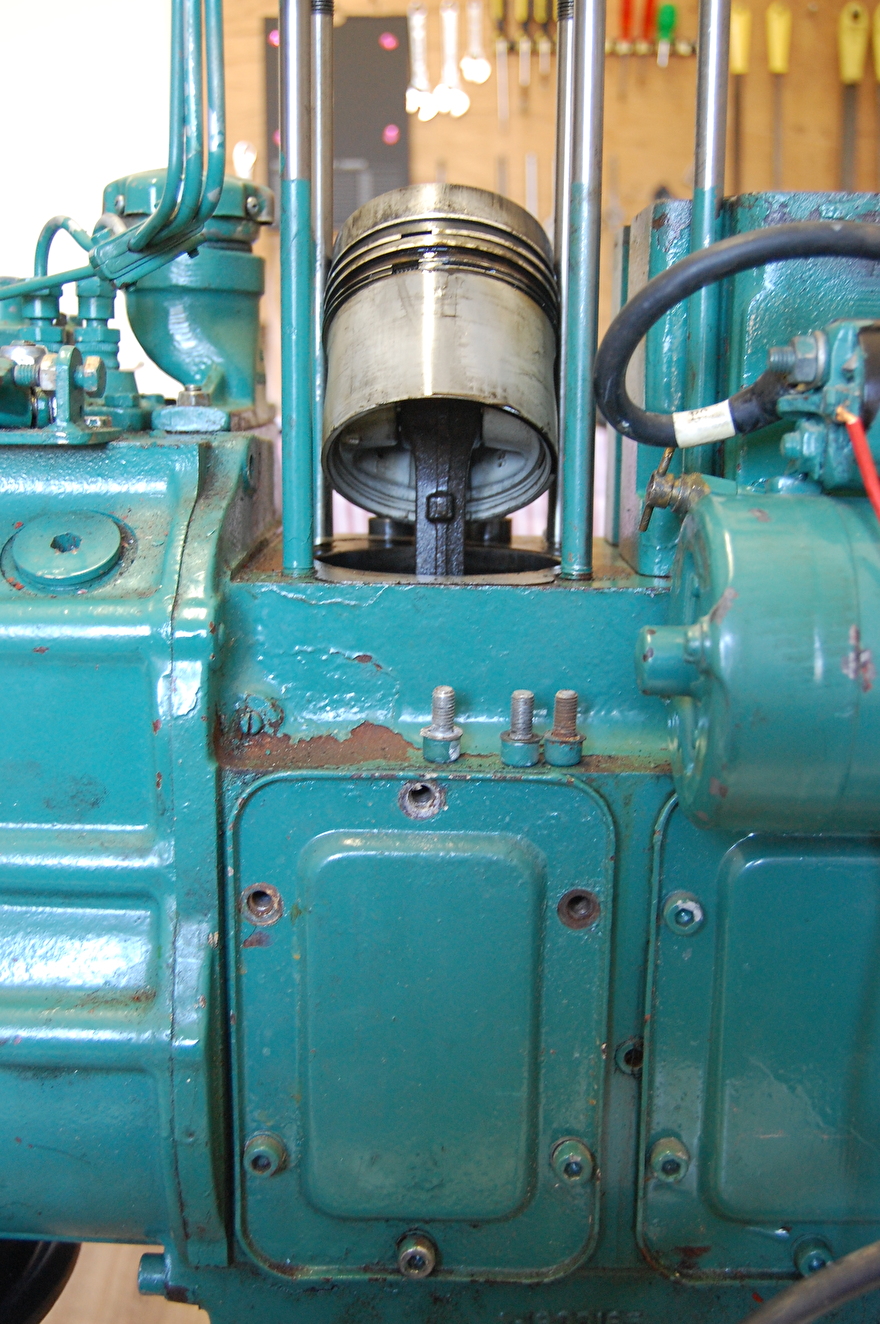
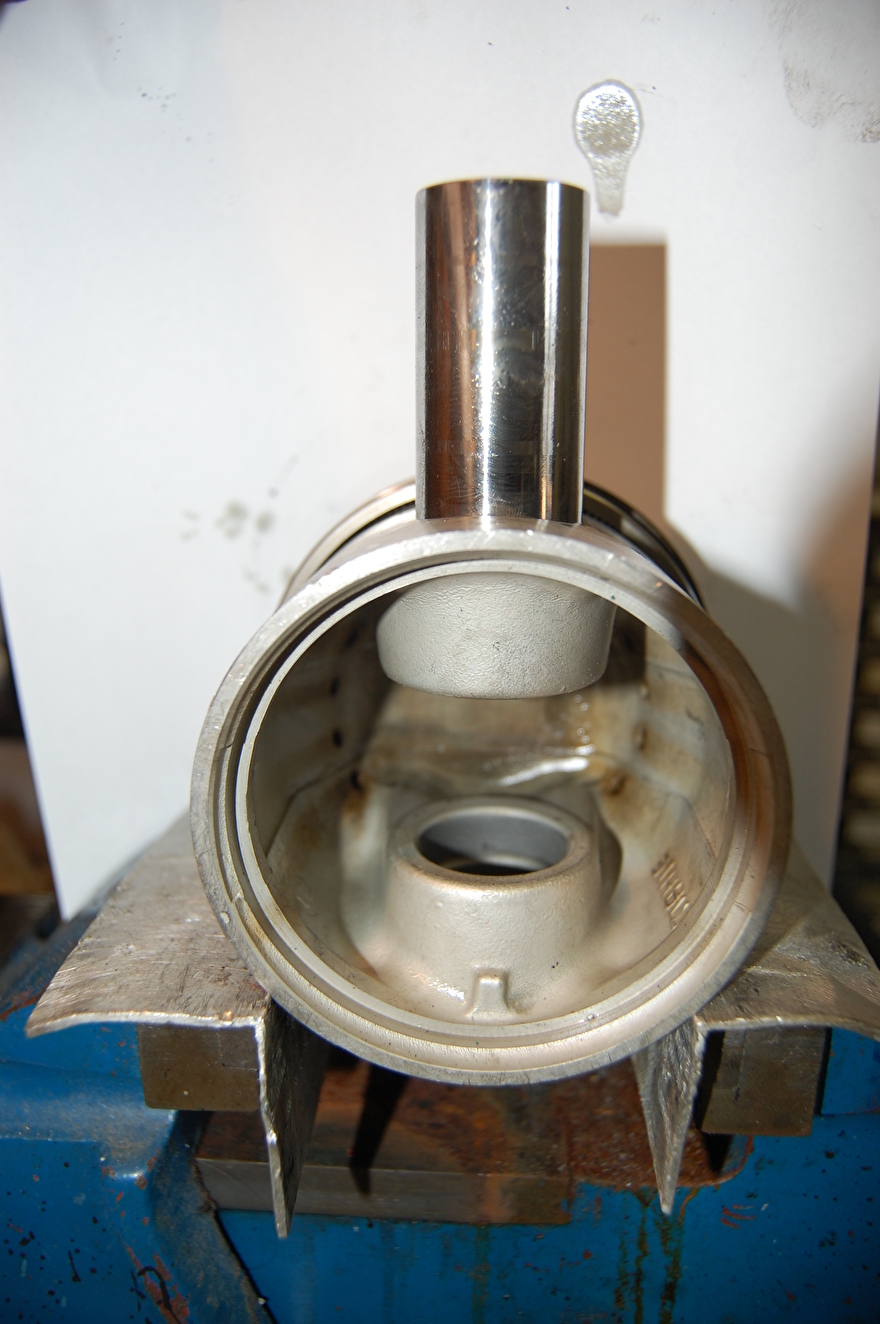
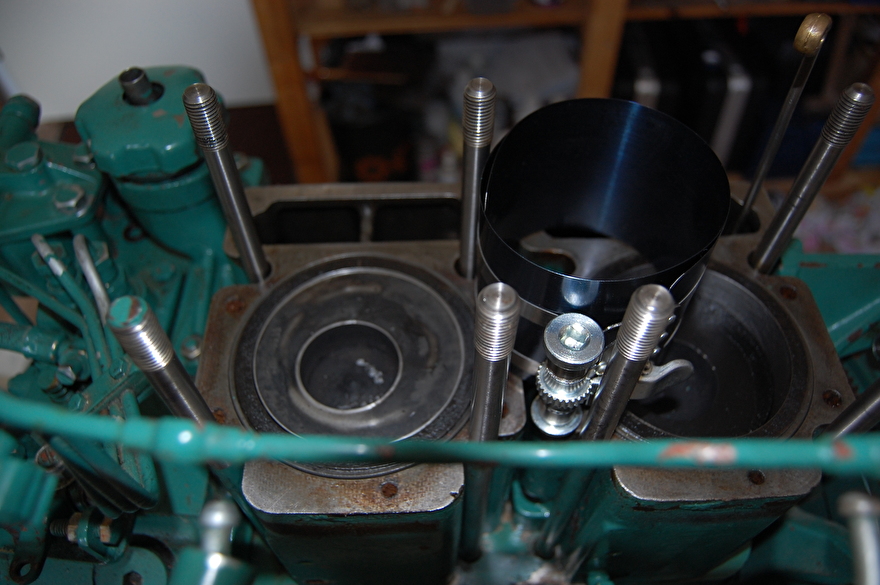
To replace the piston in the cylinder, I need a special tool that presses the piston rings so that they do not get damaged when the piston is pressed into the cylinder.
When refitting, there are a few points of attention, the piston and cylinder must be clean and the cylinder wall lubricated with oil to make assembly fun and prevent damage to the cylinder mitt.
The piston with connecting rod is pushed as far as possible into the cylinder.
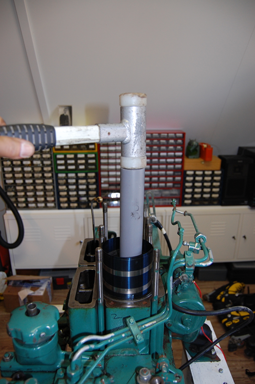
With a plastic hammer I carefully tap the piston into the cylinder.

The bearing shell is replaced and tightened with a torque wrench (65 Nm).
The crankcase cover can be placed back, but because the gasket broke when removing the crankcase cover, it must be replaced. This gasket is not cheap, a cheaper alternative is to buy a 1.5 mm piece of gasket paper and cut it to size.
Mount cylinder head.
Now that the connecting rod is back in place, it is time to replace the reconditioned head, using a fixed system to fix the head and manifold in order to prevent tearing of the head and manifold.
The head (s) has been replaced with a new head gasket and the head bolts screwed by hand (not fixed), then the exhaust nozzle is mounted, this must also be hand mounted. This has to be because the buy and manifold have to settle down, this money will only apply to engines with separate cylinder blocks the MD11 has.
Manifold hand tight with new gasket fitted.
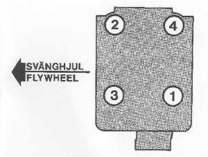
The head bolts should be tightened with a torque wrench according to the above pattern. tightening the head bolts in this case is done in 3 steps.
Step 1 30 Nm
Step 2 80 Nm
Step 3 110 Nm

The manifold is tightened with 25 Nm.
Head gasket No. 833453
Manifold gasket No. 859145
Refitting the injectors.

Before the injectors can be put back, it is important that the seat on which the injector seals is clean to prevent leakage of combustion gases.
It is best to install the fuel pipe and return pipe before the injectors are secured with the bridge, in this way you can align the injectors towards the couplings. When installing the return line, a new sealing ring must always be used.
The bridge is put back and secured with 20Nm, this is necessary to prevent deformation of the copper atomizer sleeve
After tightening the atomizer, the couplings of the pipes can be retightened. (Fixed is fixed)