This page has been translated with google translate, there may be errors in the stories.
The multimeter is an important device to find various eclectic faults on, among other things, the engine and should therefore not be missing in the tool box. The multimeter meter is, as the name implies, a versatile tool with which a large number of electrical matters can be measured. To be able to work with the multimeter, some knowledge of current, voltage and resistance is required and I will describe that in this article.
Can measure with the multimeter.
1 Electrical connection - You can see if there is a good electrical connection between a wire and a sensor, for example.
2 Resistance - You can measure transition resistance values of, for example, a bad or corroded connection.
3 Current - You can measure direct current or alternating current (Amps or milliamps)
4 Voltage - You can measure DC voltage or AC voltage (Volt or millivolt)
What kind of multimeter should I have on board.
There are many different multimeters on the market and in different price ranges, I myself use a Voltcraft multimeter e costs around 90 euros. There are also cheaper multimeters for sale at hardware stores, but beware these are usually not very accurate. If you want to measure the voltage on the poles of a battery or the charging current of a dynamo, the difference between wrong and good is only a number of tenths of volts and you would easily draw the wrong conclusion with an inaccurate voltmeter.
When purchasing a multimeter, make sure that the functions below are included.
Measuring electrical connection (contact) with a "beeper", then you can test the connection without having to look at the screen
Direct voltage (DC Volt) from 200 mV (millivolts) up to 200 Volt (D = direct)
Alternating voltage (AC Volt) from 2 Volt to 400 Volt (A = Alternating)
Direct current (DC Current) and Alternating current (AC Current) from 200 mA (milliamps) up to 20 Amps
The multimeter has a rubber bumper.
The multimeter is available in two versions.
The Switched Range where you have to set the desired measurement setting yourself.
The Auto-Range that sets itself.
How to use the multimeter.
Testing an electrical connection.
On board it is important to know whether the electrical current can flow undisturbed from the battery, via the switchboard to our device or navigation lights etc. We can test this with the multimeter. If there is electrical connection, the “resistance” of the connection is low.
Multimeters usually have a setting where you hear a beep when the connection is good.

Measure the resistance.
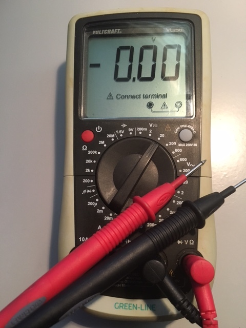
Switch the rotary switch to this position, the display shows that nothing is being measured. (1-- or OL = Open Loop).
Now hold the two probes together, the meter will now indicate something close to 0 (0.01) and a beep will sound.
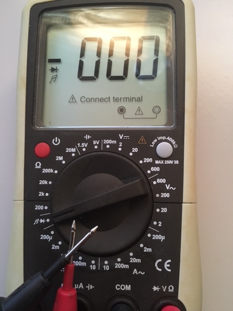
The value 0.00 indicates that the “resistance” is very low, so there is a good connection. In fact, we are measuring the resistance of the wires and the pins of the meter.
Electrical resistance is always expressed in Ω = “Ohm”. The resistance of copper wires on board is always very low, much less than 1 Ohm. If the meter indicates more than 1 Ohm or does not sound a beep, the resistance of the wire is too high or the connection is not good.
You can therefore determine whether an electrical connection is good and solid. (even if you tinker with the wire). In the same way you can measure:
Measurement of lamps or fuses.
Measure whether there is a bad contact at a connection of a plug or connector.
Measure whether there is an interruption in a wire (i.e. measure at the beginning and end of the wire)
Checking a solder connection
You can also check whether something is not connected, in other words whether the pins of a connector do not accidentally short circuit.
Or that the insulation of a wire is still good everywhere or perhaps broken.
You can also check whether there is a connection on a printed circuit board (or not) between two copper lanes.
Pay attention
You can only do the above measurements if there is no voltage on the device. In this measurement, the multimeter sends a small test voltage through the prohibition and if the word is disturbed by the external voltage or current source, the measurement is incorrect.
You can also test diodes in this position of the meter. In the reverse direction it gives no indication (in the reverse direction there is no “connection”). In the forward direction, the meter gives a beep and immediately the voltage drop (voltage loss) across the diode of approximately 0.4 - 0.6 volts.
Measuring electrical resistance.
This measurement is very similar to the previous measurement. For the measurement, there are several measuring ranges on the multimeter for different resistance values.
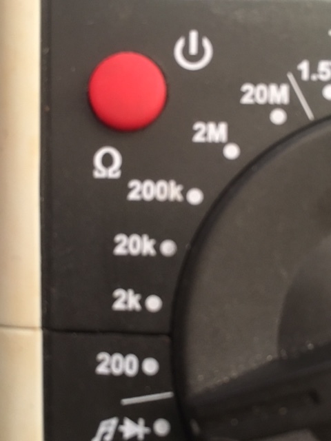
On board we usually want to know if there is a good connection between 2 points of the on-board network, and as said before, this must be well below 1 Ω. Incandescent lamps can have resistances from 1 - 100 Ω.


We want to know whether the resistance is high or low (connection or no connection), so on the 200Ω or 2kΩ position we can usually measure very well on board.
You can also measure the quality of insulation.
To do this, switch the meter to the highest range, usually this is 20 MΩ, but a single meter goes up to 200 MΩ. If electricity is leaking somewhere through the insulation, it will show as a very high but measurable resistance between the wire and ground (the hull, engine or other parts to which the electricity is leaking).
Wires lying in water (engine compartment?) Or running through the bilge sometimes have this type of insulation leak. The risk of insulation leaks is also clearly present wherever there is salt deposits. Also cables and connectors at the mast, for example. In the long run this will always cause problems if you are not there in time to remedy this.
NB: it is also nice to take both probes in your hand and see what the resistance of the human body is (This is a completely harmless test). It turns out that this resistance varies strongly between 50 kΩ (kilo-ohms) and 10MΩ (mega-ohms), depending on moisture (sweat), salt and temperature.
A few notes about measuring resistances.
1. The polarity does not matter because a “resistance” is equal in both directions. If not, we are dealing with something else, usually a “semiconductor” such as a diode or transistor. Or there is an unwanted external current or voltage somewhere that disturbs the measurement.
2. If a resistor is soldered on a printed circuit board or in a device, it is difficult to measure its own resistance, because it is usually included in a complete circuit with other electronic components. We then measure the resistance of the entire circuit and not the resistance itself.
3. If the battery in a multimeter becomes exhausted, the measurements can give errors, especially with low resistance values. (The battery must supply the “measuring current”). When measuring low resistance values, the measuring current to be supplied is proportionally high.
Color code of resistors.
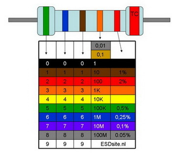
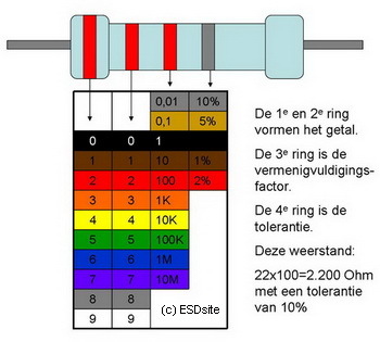
This component is named after its function. An electrical resistance restricts the passage of electrical current and causes a desired reduction in conductivity locally. The higher the resistance value, the more the current flow is limited. Conductors such as copper and aluminum have very little resistance to current. Insulators such as PVC and glass conduct almost no current because they have a very high resistance. Resistors have a predetermined value that is somewhere in between. The abbreviation for resistance as used on parts lists and diagrams is the: R (for Resistance).
Resistance R is also indicated with the Ω (ohm) sign, eg R = 512 Ω. The "regular" resistors (with runners or feet) are normally color-coded (colored rings) and are usually not very ESD sensitive.
Four-ring resistors: the first two rings determine the number, the third ring the multiplier (or how many zeros come after the number). The fourth ring is to indicate the tolerance of the resistance. See the picture. The first ring is closest to the wire feeder and / or the last ring is made wider.
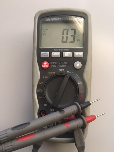
Measuring voltage (Voltage).
On our meter we have a number of measuring ranges for voltage starting at 200 mV increasing in steps of 10x to 200 or 500 Volt. There are also two scales: one for direct voltage (DC) usually with the symbol and one for alternating voltage AC usually with the symbol
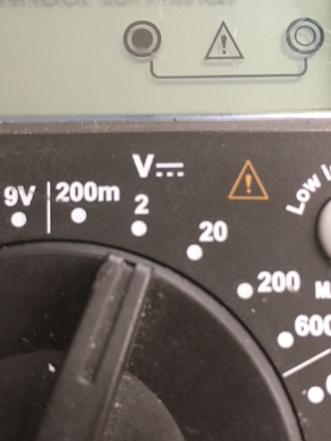
The picture above shows the DC range, or DC voltage that we have on board. When measuring an on-board network of 12 Volt, always set the meter to 20 Volt and with 24 Volt mains voltage to 200 Volt. Batteries always provide DC or DC voltage
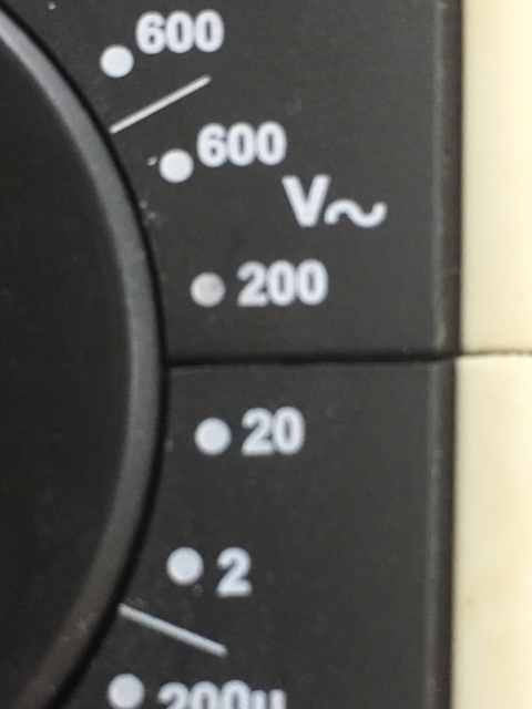
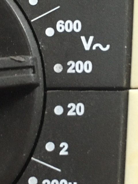
The photo above shows the measuring range of DC or alternating current. We get 230 volts from the mains (power pole in the port) but also from an inverter that we can have on board. An inverter turns 12 Volt or 24 Volt into 230 Volt. When measuring 230 volts, the same applies as 12 volts or 24 volts always choose a higher measuring range, so measure 230 volts, choose 600 volts at the meter on the picture.
Measurement accuracy.
The measurement accuracy of multimeters is approx. 0.5% of full scale. in the more expensive segment about 0.1%. When measuring on the 12 V on-board network, the inaccuracy is therefore 0.10 V resp. 0.02 V. You should keep this in mind, especially when measuring the battery voltage, especially if you want to measure the condition of the battery. The difference between a full battery and an empty battery is only 1 Volt.
An accurate multimeter to measure voltage (voltage) is important.
Measuring the on-board voltage of the batteries. This means something (but not everything) can be said about the state of charge of the battery. (For example, full = 12.6 volts and empty = 11.9 volts.)
Measure the voltage of batteries, (keep or throw away ..?)
Measuring the on-board voltage on a device, lamp or other consumer. With this you can see if there is a voltage loss in the on-board network, in other words the difference in voltage at the battery (for example 12.65 volts) and the voltage on the device (11.90 volts) shows that there is a 0.75 volt voltage loss somewhere is. This voltage loss must of course be as small as possible. Voltage loss is power loss. This is very important with navigation lights. Because voltage loss is brightness reduction.
Measure whether the battery voltage of the on-board network does not drop too much when switching on consumers. This can be an indication of obsolete batteries.
Measure whether there is voltage on a device, (if that device should work but it doesn't work)
Checking the alternator. If it recharges properly, the battery voltage gradually rises to 13.5 - 14.2 volts due to the charging effect of the alternator.
Measuring mains voltage or checking the 220 Volt inverter (WARNING! High voltage)
Measuring in practice.
You can only measure voltage (in volts) between two points. The wiring does not have to be disconnected. One of the measuring points is always low (the minus or the earth) and the other point high (the plus), and that immediately indicates the direction in which the current is flowing (or will flow if a connection is established).
You can only measure voltage (in Volts) between two points. The wiring does not have to be disconnected. One of the measuring points is always low (the minus or the earth) and the other point high (the plus), and that immediately indicates the direction in which the current is flowing (or will flow if the connection is established).
Measuring range.
If the red and black test leads are reversed, or if there is a negative voltage, the meter will indicate this by putting a - (minus) before the number. So swap cables or measuring points. If the meter indicates 0.00 V then there is no voltage.
Measure current:
Measuring current in an electrical circuit usually requires disconnecting this circuit first and including the multimeter in the circuit. The current to be measured then flows through the meter. With some meters it is also necessary to plug the test leads into another connection. The black lead remains in the COM jack, but the red lead must be plugged into the (μA / mA) connection. For the measurement of high currents, there is also a separate connection usually marked with (10 A or 20A). The black cable must always remain plugged into the COM connection.
For the alternating measurement of current or voltage, the red test lead must therefore always be plugged from the V to A connection and vice versa. Forgetting this is a common mistake. When measuring voltage with the test leads accidentally still in the connection> μA / mA, the fuse in the meter will almost certainly blow. The meter is usually protected against measuring excessive currents with a fuse. It is located inside the meter, so if it stops working no Amp or milliAmp, open the meter and replace the fuse.
In almost all cases on board we have to deal with measuring higher currents. In that case, plug the test leads into the 20A connection. It is not protected with a fuse, so pay attention! For example, when you try to measure the battery voltage with the meter still connected to a 20A power socket, spectacular sparks and smoke are the result.
You can also measure whether current is flowing through a pipe without disconnecting it. If current flows through a copper pipe, there is always a small voltage difference (or voltage loss) across this pipe and you can measure that too. In that case, set the meter to 200 mV and measure the voltage at the beginning and end of the wire. If there is a measurable voltage difference, and the wire is not broken, a current will flow through this wire! The amperage is proportional to the resistance of the wire and the measured voltage (Ohm's law)
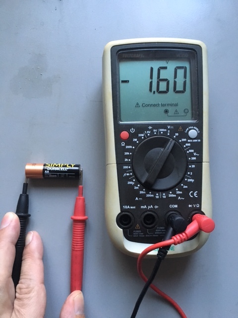
You can also check a battery with a multimeter, for example one of 1.5 volts.
Measure battery.
Black test lead in COMM and the and the red in V, you can then voltage with on the pollen. Between 12.3 and 12.7 volts the battery is full and at 11.6 the battery is empty.
Battery charge status | % discharged | Rest Voltage in volts | ||
100% | 0 | 12,72, | ||
80% | 20 | 12,52 | ||
60% | 40 | 12,31 | ||
40% | 60 | 12.09 | ||
20% | 80 | 11.88 | ||
0% | 100 | 11,64 |
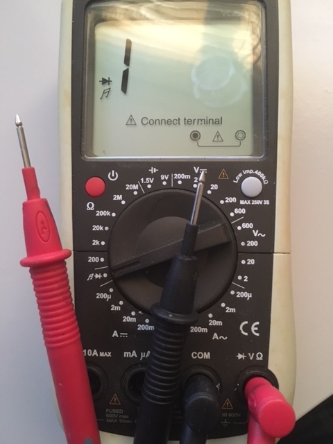
Measure the sensor.
With a multimeter you can also measure a sensor if you set the multimeter to resistance.
I have a sensor that makes contact at a certain temperature, there is a light on the dashboard and a sound signal is given when the contact is made in the sensor.
The test setup on photo 1 shows when the sensor is not making contact, multimeter is not 1 on. In picture 2 the multimeter indicates a resistance of 0 and thus makes contact. Contact with this sensor is made at a temperature of 85 degrees.


Measuring alternating current or direct current.
On board we almost always measure on DC, unless we want to measure on shore power, a generator or a 230 volt inverter. They are always AC.
Always check before you start measuring whether the meter is correctly set to AC or DC. Nothing breaks, but the meter gives incomprehensible results. Usually this can be set with the central rotary knob, but sometimes there is a separate switch or push button on the meter.
Appendix: The concepts Voltage, Current and Resistance.
Voltage and current.
You could consider voltage as the “potential energy” of the electricity. The higher the potential energy, the higher the voltage (also called potential or voltage). Some people compare electricity to the flow of water through a garden hose. The higher the pressure in the hose, the greater the “tension”. So the tube or hose will also have to be stronger to withstand the pressure, (and the insulation of the wire will have to be better (or thicker) to keep the electricity in the wire). The voltage (or pressure) can sometimes be very high without anything flowing because, for example, a tap is closed at the end of the hose or the wire is insulated at the end. A higher pressure can also cause more water to flow through the hose when the tap is open at the end (there is a low resistance at the end). So here too: as the name implies: with a low resistance, the current usually increases.
Voltage is the driving force of electricity. Just as a water pump increases pressure and causes water to flow through a tube, a battery, accumulator or dynamo will provide a voltage that pushes the electricity through the wires.
You could consider voltage as the “potential energy” of the electricity. The higher the potential energy, the higher the voltage (also called potential or voltage). Some people compare electricity to the flow of water through a So “Voltage” is comparable to the pressure (Bar) in the pipe, and is always measured in Volts
And “Current” is therefore comparable to the amount of water (liters per minute) that flows through a tube and is always measured in Amps
Of course you can also express this in millivolt mV or milliampere mA, depending on the size
The confusing thing is that by many, the terms voltage and current are often used incorrectly and interchangeably. But with the mnemonic of the garden hose it is easy to remember.
Direct current and alternating current.
Direct current (or rather direct voltage) comes from batteries, accumulators, and most mains adapters. The voltage has a fixed value and is more or less constant over time.
The symbol for this is
Alternating current (or rather alternating voltage) comes from the mains at home or from the inverter on board. The voltage here varies continuously between + and - and usually has a sinusoidal (wave-shaped) course. Hence the symbol for alternating current
Note: With some inverters the gradient is more square.
In our home mains, the voltage fluctuates exactly 50 times per second; sometimes this can be perceived as a slight flickering of the light from fluorescent tubes.
The big advantage of alternating current is that it is very easy to convert to another voltage with the help of a transformer. That is not possible with direct current.
NB: There are so-called DC / DC converters, but internally the DC voltage is always first converted into AC voltage, transformed to a different voltage level, and then converted back into DC voltage of another voltage.
In general, the negative values and the positive values of the AC voltage will be the same, so that the average voltage is exactly zero. With a meter set to a DC measuring range, this will also be indicated as a value of zero. In some cases the voltage curve is a combination of direct and alternating current; this is beyond the scope of this story and is not important on board.
Power f380.
A special case of alternating current is “three-phase current”, also called “three-phase” current or “three-phase current”. The electrical energy is transported here over three conductors instead of two conductors. Because of its efficiency, it is always the case with large-scale power generation, distribution and transport pipelines or heavy drives - hence the name.
Not important for on board.
Resistance.
Resistance is a property of the material. Metals are all electrically conductive and each has a specific resistance. Copper has a very low resistance, silver and gold even slightly lower. Aluminum has a slightly higher resistance than copper, but due to its much lower price, it is often used for long-distance transport lines. When current flows through an electrical resistor, this always results in energy loss: the resistor becomes warm as more current flows through it.
When we want to create a specific “resistor” (which is necessary for electronic circuits to work), we usually use carbon or a very thin metal film.
With such resistors we can accurately calculate the voltage levels in a device and set it to the desired value.
A special form of a resistor is a “potentiometer”, in fact a resistor with a tap at an adjustable location, with which the resistance can be varied continuously and voltage levels can be set continuously. A potentiometer is often used as a volume knob on radios or amplifiers (when there were no MP3 players yet)
Materials with a high to very high resistance (plastic, glass, ceramics) are used as insulation material. In practice, they have an infinitely high resistance for us.
Ohm's law.
All this has been discovered and systematically investigated by Ohm and then later laid down in the law named after him:
V = I x R or Voltage (V) = Current (I) x Resistance (R).
A good understanding of Ohm's law is unfortunately indispensable for measuring and understanding electrical phenomena. Fortunately, Ohm's Law is not difficult to understand or remember (using the running water model)
If two of the three quantities are known (or measured), you can always calculate the third quantity. With a multimeter you can always measure all three quantities, so it is always possible (also on board) to know what is happening in an electrical circuit.
You can also write Ohm's law as.
I = V / R or the current (I) is proportional to the applied voltage and inversely proportional to the resistance or R = V / I with this you can calculate how much the resistance (R) over a circuit if the voltage and the current are known to be.
Is electricity dangerous?
A higher voltage V at a constant resistance R leads to a higher current I. This is also the reason that high voltages can be dangerous or even deadly for humans, because it is not the voltage but the current through your body that is dangerous. Voltages below 50 volts are in no way dangerous, you will only feel a slight stimulation. Between 50 and 100 volts the current through your body increases and this stimulation becomes annoying, and above 100 volts the current intensity becomes downright dangerous, especially in moist conditions and when the resistance R of the body is low.